中文简体
 عربى
Content
- 1 1. Technical Architecture and Key Components of Flat Knitting Machines
- 2 2. Single System vs. Double System vs. Triple System Machines
- 3 3. Multi-Gauge Technology vs. Fixed Single-Gauge Equipment
- 4 4. Motor-Driven Sinker Technology and Dynamic Stitch Control
- 5 5. Comprehensive Preventive Maintenance Guidelines for Factory Operators
- 6 6. ROI and Total Cost of Ownership Evaluation Framework
- 7 7. Troubleshooting Common Production Defects
- 8 8. Industry Standard FAQs
- 9 9. Academic and Industrial References
The global textile manufacturing industry has undergone a radical transformation over the past few decades. At the forefront of this revolution is the Computerized Flat Knitting Machine, a highly versatile piece of equipment that has largely replaced traditional manual and mechanical knitting beds. For textile producers, garment factories, and industrial fabric manufacturers, selecting the correct machinery is crucial for maintaining production efficiency, fabric quality, and operational profitability. This article provides a comprehensive technical breakdown of computerized flat knitting technology, comparing primary drive systems, evaluating multi-gauge versus single-gauge capabilities, outlining maintenance protocols, and detailing the ROI parameters necessary for industrial buyers.
1. Technical Architecture and Key Components of Flat Knitting Machines
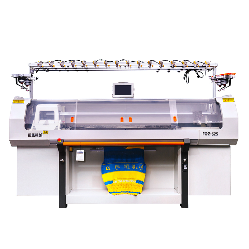
Understanding the internal mechanisms of a computerized flat knitting machine is essential for optimizing fabric structure and machine performance. Modern flat knitting machines consist of several interconnected sub-systems that synchronize mechanical motion with digital design files.
1.1 Primary Sub-Systems Breakdown
| Component | Primary Function | Operational Impact |
|---|---|---|
| Needle Bed and Latch Needles | Holds the needles in precision-milled trick slots and controls loop formation. | Determines gauge accuracy, stitch size consistency, and fabric width capacity. |
| Carriage System | Traverses horizontally across the needle bed to drive needle movement. | Houses the cam systems; directly dictates knitting speed and pattern complexity. |
| Electromagnetic Selectors | Selects individual needles according to design data input. | Enables full-fashioning, jacquard, and three-dimensional structural knitting. |
| Yarn Feeders and Tensioners | Delivers yarn at precise tensions to the active needle hooks. | Prevents yarn breakage, uneven tension, and fabric defects during high-speed runs. |
| Main Take-down Roller System | Applies uniform downward tension on the knitted fabric as it is produced. | Ensures dimensional stability and prevents loop distortion across the bed. |
1.2 Mechanics of Loop Formation and Cam Timing
The interaction between the carriage assembly and the needle bed is governed by precise timing mechanisms. Electromagnetic selectors activate needle jacks based on rasterized pattern files. As the carriage moves across the bed, specialized cam tracks push selected needles upward into tuck, knit, or miss positions. The precise geometry of these cams determines how smoothly the yarn is converted into intermeshed loops, directly affecting the tactile feel and tensile strength of the finished textile.
2. Single System vs. Double System vs. Triple System Machines
When selecting a computerized flat knitting machine, one of the primary hardware decisions involves the number of knitting systems housed within the carriage. A system refers to a complete set of knitting cams capable of forming stitches during a single pass across the needle bed.
2.1 System Architecture Comparison
Single System Machines
Single-system machines feature one set of cams per carriage. They are lightweight, highly reliable, and relatively simple to maintain. Because the carriage is light, direction changes at the end of each stroke occur rapidly with minimal mechanical stress. These machines excel at producing basic structures, small batch sampling, and simple trims, collars, and cuffs. However, their overall output volume is lower compared to multi-system configurations.
Double System Machines
Double-system machines incorporate two complete cam sets within a single carriage. This configuration allows the machine to perform two rows of knitting or a combination of knitting and transferring in a single traverse stroke. Double-system units represent the industry standard for general sweater production, balancing high output rates with structural versatility. They offer superior efficiency when executing complex cable patterns, full-fashioned panels, and light jacquards.
Triple System Machines
Triple-system setups feature three independent cam sets. These high-productivity machines are engineered for large-scale industrial manufacturing where volume is the critical metric. A triple-system machine can process intricate structures—such as simultaneous rib knitting, transferring, and pointelle stitching—in significantly fewer carriage passes than a single or double-system alternative. While they offer peak efficiency, they require skilled technicians to adjust yarn tension and resolve mechanical jams due to the density of components within the carriage.
2.2 Production Performance and System Selection Matrix
| Machine System Type | Production Capacity | Maintenance Complexity | Ideal Application Focus |
|---|---|---|---|
| Single System | Low to Moderate | Low | Trims, Collars, Cuffs, Sampling, Simple Panels |
| Double System | High | Moderate | Standard Sweaters, Full-Fashioned Apparel, Ribbing |
| Triple System | Very High | High | Complex Jacquards, High-Volume Garment Panels |
3. Multi-Gauge Technology vs. Fixed Single-Gauge Equipment
Needle bed gauge defines the density of needles per inch (npi) along the bed. Traditional flat knitting machinery was strictly built on a fixed single-gauge architecture, meaning a 7-gauge machine could only operate with 7-gauge needle spacing and corresponding yarn weights. Modern manufacturing demands greater flexibility, driving the adoption of multi-gauge (variable gauge) technology.
3.1 Fixed Single-Gauge Systems
Fixed-gauge machines utilize uniform needle hook sizes and trick bed dimensions. Every needle slot is identical, designed specifically for a narrow range of yarn counts. Fixed-gauge machines offer exceptional dimensional precision and loop uniformity when running continuous high-volume orders of a standard yarn weight. Their mechanical simplicity minimizes needle wear and reduces initial capital expenditure per machine unit.
3.2 Multi-Gauge (Variable Gauge) Systems
Multi-gauge machines feature specially designed needle beds and sinker mechanisms capable of handling multiple yarn thicknesses on the same needle bed without physical bed replacement. A single multi-gauge machine—for instance, a gauge rated at 12G—can knit using 12G yarns, 14G yarns, or even coarser yarns by selectively skipping needles or using specialized needle hook geometries. This capability allows manufacturers to produce gauge-blended garments, transition between lightweight and heavyweight collections on the same machine, and rapidly adjust to changing seasonal fashion trends without investing in new hardware beds.
3.3 Feature Comparison: Single-Gauge vs. Multi-Gauge
| Feature Parameter | Fixed Single-Gauge | Multi-Gauge (Variable Gauge) |
|---|---|---|
| Fabric Versatility | Limited to specific yarn count range | High; handles coarse to fine yarns on one bed |
| Setup Time for Style Changes | Moderate (Requires yarn and tension tuning) | Minimal (Digital adjustment via control software) |
| Machine Capital Cost | Lower initial investment | Higher initial investment |
| Stitch Precision | Maximum loop uniformity for fixed count | Slightly wider loop tolerance across variations |
4. Motor-Driven Sinker Technology and Dynamic Stitch Control
Two critical mechanical innovations that separate basic computerized flat knitting machines from high-performance models are motor-driven sinker mechanisms and dynamic stitch control systems.
4.1 Motor-Driven Sinker Technology
Traditional flat knitting machines relied on fixed mechanical springs or passive presser feet to hold down fabric loops as the needles rose to take new yarn. In contrast, advanced computerized models utilize independently motorized sinker systems. Each sinker is controlled by a micro-step motor or direct solenoid actuator, allowing variable hold-down force across different sections of the fabric bed.
This dynamic capability is vital when knitting complex three-dimensional structures, such as shoe uppers, orthopedic supports, or fully integrated seamless garments. By applying precise, variable pressure to individual loops, motorized sinkers prevent fabric lifting, eliminate loop distortions, and allow clean knitting on needle combinations that would otherwise cause heavy yarn strain or fabric jamming.
4.2 Dynamic Stitch Control Systems (DSCS)
Consistent fabric dimensions depend on maintaining uniform yarn consumption across thousands of rows of knitting. Yarns naturally suffer from variances in friction, elasticity, moisture content, and package winding tension. Dynamic Stitch Control Systems continuously monitor yarn intake using optical sensors or mechanical encoder wheels.
If the system detects that a stitch course is consuming more or less yarn than specified by the design file, the step motors instantly adjust the depth of the stitch cams in real time. This automated feedback loop keeps garment panel dimensions within sub-millimeter tolerances, ensuring that front panels, back panels, and sleeves match perfectly during assembly without requiring manual post-knit heat shaping or cutting adjustment.
4.3 Closed-Loop Control Process Architecture
5. Comprehensive Preventive Maintenance Guidelines for Factory Operators
A high-precision computerized flat knitting machine operates under constant vibration, thermal friction, and airborne micro-fiber exposure. Implementing a disciplined maintenance routine directly prolongs needle bed lifespan, preserves electronic control units, and drastically reduces defective product rates.
5.1 Daily Shift Operations Checklist
Before launching production shifts, operators must perform systematic preliminary checks to ensure operational safety and fabric consistency.
| Component Area | Inspection Point | Corrective Action Required |
|---|---|---|
| Yarn Paths & Feeders | Check for lint accumulation, burrs, and grooves. | Clean with compressed air; replace worn eyelets immediately. |
| Needle Bed Trick Slots | Look for bent needles, broken latches, or metallic dust. | Replace damaged needles; vacuum fluff from trick grooves. |
| Take-down Rollers | Examine roller surface for yarn wrap-around or residue build-up. | Clear wrapped threads; clean rubber surfaces with approved solvent. |
| Safety Light Curtains | Verify automatic emergency stop response when beam is broken. | Realign optical sensors; clear obstructions from detection zone. |
5.2 Scheduled Weekly and Monthly Deep Maintenance Protocols
Sub-surface components require scheduled teardowns and deep cleaning cycles to prevent catastrophic mechanical failure during continuous operations.
Weekly Maintenance Protocols
Every week, technicians must remove needle bed cover plates and utilize high-pressure air blowing systems combined with industrial vacuum units to strip fiber dust out of the needle tracks. Fiber accumulation inside needle tricks absorbs lubrication oil, forming an abrasive sludge that wears down needle butts and distorts carriage motion profiles.
Monthly Maintenance Protocols
On a monthly schedule, operators must check drive belt tensioning across carriage servomotors, clear cooling fan filter screens on industrial computer enclosures, inspect grease levels inside main drive gearboxes, and flush old lubricant from central oil pump lines. Utilizing original manufacturer-specified synthetic lubricants is essential; lower-grade oil can oxidize under high friction temperatures, causing electrical sensor failures and gumming up selector solenoids.
6. ROI and Total Cost of Ownership Evaluation Framework
Investing in computerized flat knitting machinery requires evaluating operational expenditure alongside long-term yield increases. Industrial buyers must weigh initial acquisition prices against energy consumption, production speed improvements, scrap rate reductions, and labor costs.
6.1 Cost-Benefit Financial Breakdown
| Cost Component | Traditional Mechanical / Basic Machines | Modern Computerized Flat Knitting Machine |
|---|---|---|
| Capital Expenditure (CapEx) | Lower upfront investment per unit | Higher upfront unit cost |
| Labor Requirement | 1 operator per 2 to 4 machines | 1 operator per 8 to 12 machines |
| Production Yield Speed | Standard fixed stroke rate | High variable speed with rapid carriage turnarounds |
| Garment Waste Factor | Higher waste from manual cutting (Cut & Sew) | Minimal waste via Full-Fashioned / WholeGarment modes |
| Energy Consumption Rate | Constant mechanical load draw | Optimized servo motors with energy regeneration brake units |
6.2 Calculating Payback Period and Operational Savings
To quantify the Return on Investment, plant managers should utilize a structured financial recovery formula comparing historical production costs against post-automation metrics:
Payback Period (Months) = Net Capital Investment / Monthly Operational Savings
Where Monthly Operational Savings equals the combined reduction in labor expenditures, lowered yarn scrap material costs, reduced electricity consumption, and increased billable unit output per shift. On average, upgrading from legacy mechanical units to modern multi-gauge computerized systems yields complete capital cost recovery within 14 to 22 operational months depending on production factory capacity utilization rates.
7. Troubleshooting Common Production Defects
Even high-end computerized machinery encounters operational glitches caused by raw material variations or mechanical wear. Fast diagnosis and resolution preserve production schedules.
7.1 Drop Stitches and Unintended Holes
Unintended holes in the knit structure typically stem from incorrect yarn tension, bent needle latches, or misaligned yarn feeder positions. If a needle latch fails to open fully during carriage movement, it misses the newly fed yarn strand, resulting in a dropped loop. Technicians should verify feeder height alignment relative to the needle hook top edge and clear any fiber knots inside tension disc plates.
7.2 Horizontal Barre and Banding Marks
Visible horizontal lines running across the fabric usually signal uneven yarn consumption or mechanical resistance in specific needle trick slots. Check the Dynamic Stitch Control System data logs to identify if yarn input varies across specific strokes. Clean the affected bed section, replace worn or sluggish needles, and verify that carriage drive belt tension remains uniform across the full stroke length.
7.3 Yarn Snagging and Needle Breakage
Frequent needle latch breakage indicates excessive yarn tension, overly tight stitch cam settings, or incorrect sinker timing relative to carriage movement. Inspect yarn guides for deep mechanical grooves cut by hard synthetic yarns, decrease stitch cam down-stroke depth slightly, and ensure the automatic central oil lubrication pump is pumping adequate oil volume to the needle bed surface.
8. Industry Standard FAQs
Question 1: What is the primary operational difference between full-fashioned knitting and cut-and-sew manufacturing on flat knitting machines?
Answer: Full-fashioned knitting shapes garment components (such as sleeves, front panels, and back panels) directly on the machine needle bed by increasing or decreasing active loop counts. This produces finished pattern shapes ready for linking, virtually eliminating fabric cutting waste. Cut-and-sew manufacturing knits continuous square or rectangular fabric sheets that must be manually cut with templates, creating substantial yarn scrap waste during final assembly.
Question 2: How does yarn count selection relate directly to needle bed gauge selection?
Answer: Needle bed gauge defines the physical space between needles. Finer gauges (e.g., 14G, 16G, 18G) require finer, thinner yarns (high metric count yarn, such as Nm 2/48 to Nm 2/60) to prevent needle jam events and loop distortion. Coarser gauges (e.g., 3G, 5G, 7G) require thicker, heavier yarns (low metric count yarn, such as Nm 2/3 to Nm 2/8) to form balanced loops that properly fill the wider inter-needle gap distance without leaving loose, unstructured fabric grids.
Question 3: Why are servo motor carriage drives preferred over traditional mechanical belt systems in modern machines?
Answer: Servo motor drives allow precise, non-linear velocity control over carriage movements. They allow variable stroke widths, meaning the carriage turns around immediately after clearing the active knitting area rather than traversing the full physical length of the needle bed. This dynamic stroke minimization shortens production cycle times, decreases mechanical vibration stress, and lowers overall electrical consumption by adjusting motor torque output based on load requirements.
Question 4: What steps are required when transitioning a computerized flat knitting machine from processing natural wool yarns to synthetic filaments like polyester or nylon?
Answer: When switching from natural fibers to synthetic filament yarns, operators must adjust yarn tensioners to accommodate lower yarn surface friction, calibrate sinker pressure to prevent filament snagging, replace ceramic yarn guides if worn or grooved by hard synthetics, increase static electricity discharge grounding protocols across the machine frame, and adjust dynamic stitch control sensor parameters to handle high elasticity profiles without misinterpreting thread stretches as feeding failures.
Question 5: What causes needle latch oxidation and how can operators prevent chemical degradation of needle beds?
Answer: Needle latch oxidation occurs when ambient factory humidity levels exceed recommended operating limits (above 65% relative humidity) or when low-grade, non-emulsifying lubrication oils are used. Fiber fly traps moisture against raw steel surfaces, accelerating rust formation. To prevent oxidation, maintain controlled factory environmental humidity (50-60% RH), install active air filtration units, and strictly apply high-purity synthetic needle oils that contain rust-inhibiting additives and moisture-dispersing formulations.
9. Academic and Industrial References
Reference 1: Spencer, D. J. (2001). Knitting Technology: A Comprehensive Handbook to Fabric Formation and Machinery Structure (3rd ed.). Woodhead Publishing in Textiles. Cambridge, UK.
Reference 2: Ray, S. C. (2012). Fundamentals and Advances in Knitting Technology. Woodhead Publishing India. New Delhi, India.
Reference 3: Au, K. F. (Ed.). (2011). Advances in Knitting Technology. Woodhead Publishing Series in Textiles. Elsevier Science Ltd. Oxford, UK.
Reference 4: Brackenbury, T. (1992). Knitted Clothing Technology. Blackwell Scientific Publications. London, UK.
Reference 5: Hunter, L. (2004). Process Control in Knitting Manufacturing. Textile Progress Journal, 36(3), 1-84. Taylor & Francis. London, UK.